September 28, 2023
What Is the Science Behind Push Button Switches and How They Work
Share
BuildWithFlux


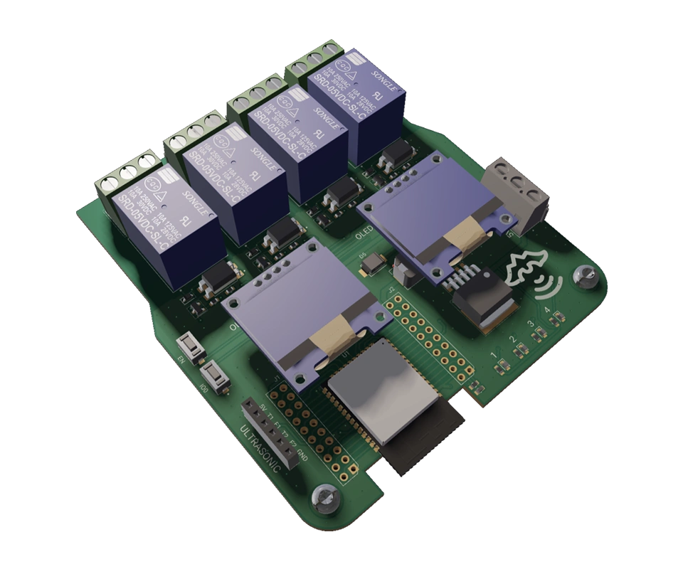
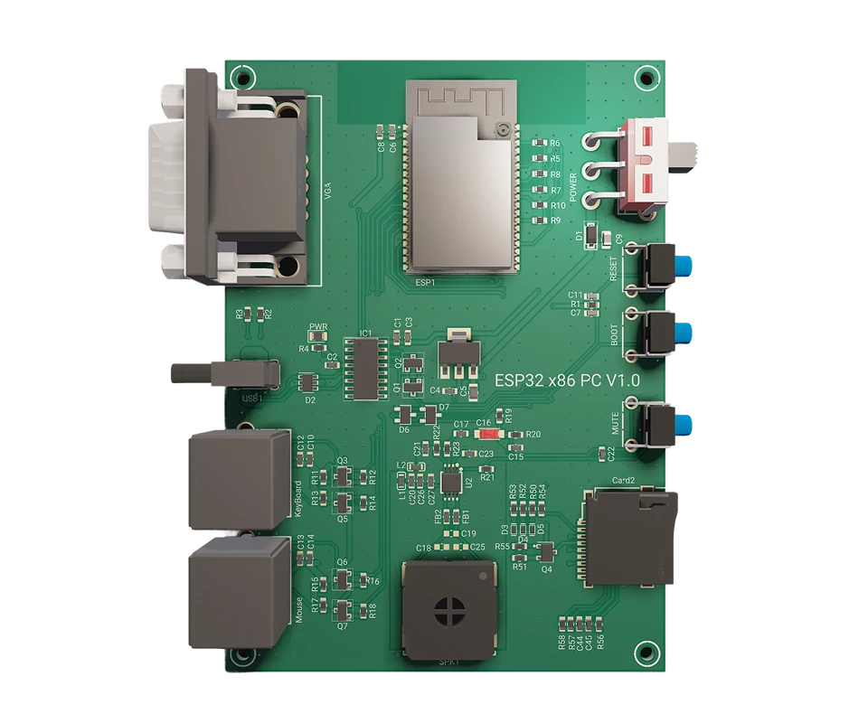
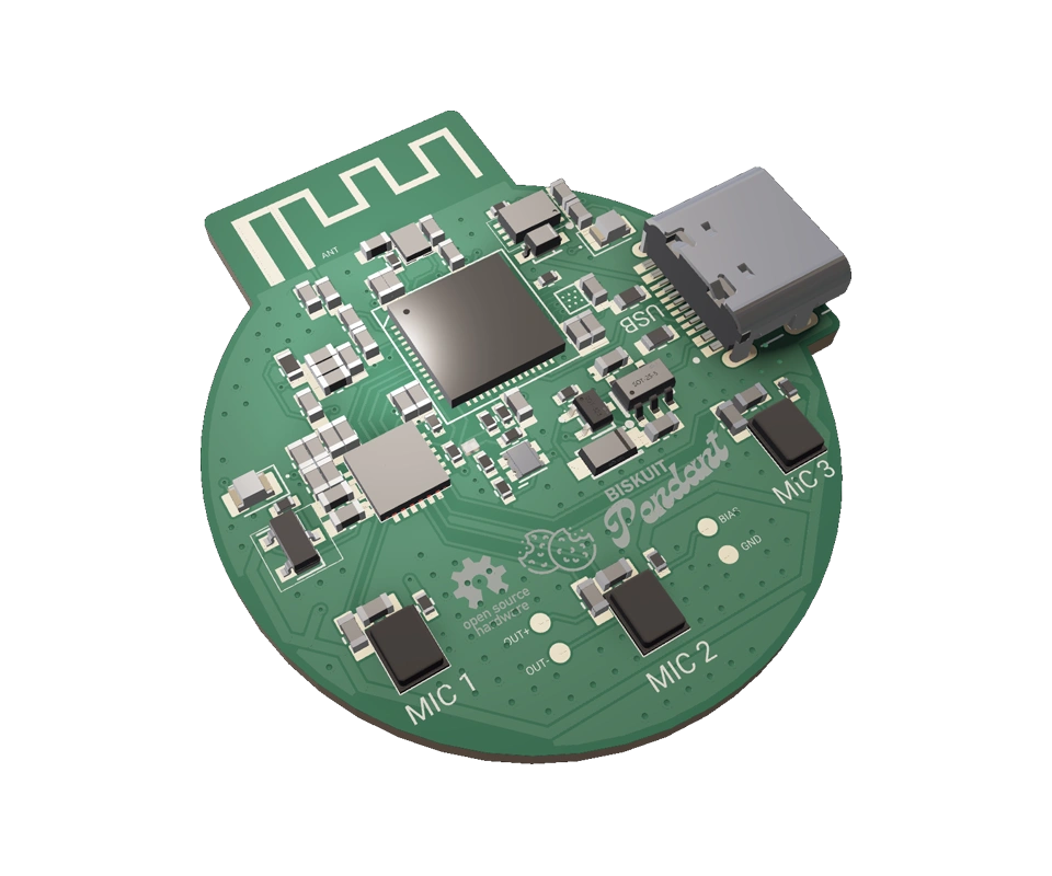
A curated collection of PCB and hardware projects crafted by our talented Flux community.
A push button switch is a simple yet versatile electrical switch used to open or close an electrical circuit by pressing a button. These switches come in various shapes and sizes, but they all share the same fundamental principle: pressing the button changes the switch's state from open to closed or vice versa. This action, often accompanied by a satisfying click, completes or breaks an electrical path, enabling or disabling a device's function.

Understanding how a push button switch works requires a closer look at its internal components. Here is a simplified breakdown:
Push button switches can vary significantly in their configurations, and understanding these distinctions is crucial when designing electronic circuits. Here are some common types:
The SPST push button switch is our first type of single pole switch. It is the simplest type, featuring only one set of contacts—ideal for basic on/off functions and is often found in household light switches.
An SPDT push button switch, another single pole switch type, offers two sets of contacts, allowing it to act as a toggle switch between two different electrical paths. This is useful in scenarios where you need to choose between two actions with a single button press.
DPST push button switches have two sets of contacts, each operating independently. They are commonly used in situations requiring two separate circuits to be controlled simultaneously.
Push button switches can be further categorized as latching or momentary. Latching switches maintain their state after being pressed, while momentary switches return to their original state when released. These distinctions are important depending on the intended function of the switch.
One common issue with push button switches is debouncing. When you press or release a button, it can create rapid fluctuations in the electrical signal due to the mechanical nature of the switch. This bouncing generates a series of electrical spikes and dips, making it challenging for the connected circuitry to interpret the intended input accurately. Debouncing is the process of filtering out these erratic signals to ensure a clean and stable transition between states. Achieving this involves employing techniques such as:
In scenarios where users might rapidly press a button, it's essential to filter out unintended or extraneous signals. This can be achieved through electronic circuitry that detects and ignores rapid successive button presses, ensuring that only intentional inputs are registered. Here's how it works:
Pull-up and pull-down resistors play a crucial role in pushbutton switch circuits, especially in microcontroller-based designs. These resistors are used to ensure that the input signal to the microcontroller is in a known state when the button is not pressed.
We see pull-up and pull-down applications in software as well when we set default values or states for variables, flags, or configuration options—specifying how a particular variable or option should behave when it is not explicitly set.
Push button switches find applications in various domains:
In electronic schematics, push button switches are represented using specific symbols. The most common symbols for push buttons include:

Whether you're turning on a light, starting your car, or operating heavy machinery, push button switches play a crucial role. Understanding their science and functionality is essential for anyone working with electronic circuits. So now next time you press that unassuming button, you can understand the intricate science behind it.
A push button switch is a simple yet versatile electrical switch used to open or close an electrical circuit by pressing a button. These switches come in various shapes and sizes, but they all share the same fundamental principle: pressing the button changes the switch's state from open to closed or vice versa. This action, often accompanied by a satisfying click, completes or breaks an electrical path, enabling or disabling a device's function.
Understanding how a push button switch works requires a closer look at its internal components. Here is a simplified breakdown:
Push button switches can vary significantly in their configurations, and understanding these distinctions is crucial when designing electronic circuits. Here are some common types:
The SPST push button switch is our first type of single pole switch. It is the simplest type, featuring only one set of contacts—ideal for basic on/off functions and is often found in household light switches.
An SPDT push button switch, another single pole switch type, offers two sets of contacts, allowing it to act as a toggle switch between two different electrical paths. This is useful in scenarios where you need to choose between two actions with a single button press.
DPST push button switches have two sets of contacts, each operating independently. They are commonly used in situations requiring two separate circuits to be controlled simultaneously.
Push button switches can be further categorized as latching or momentary. Latching switches maintain their state after being pressed, while momentary switches return to their original state when released. These distinctions are important depending on the intended function of the switch.
One common issue with push button switches is debouncing. When you press or release a button, it can create rapid fluctuations in the electrical signal due to the mechanical nature of the switch. This bouncing generates a series of electrical spikes and dips, making it challenging for the connected circuitry to interpret the intended input accurately. Debouncing is the process of filtering out these erratic signals to ensure a clean and stable transition between states. Achieving this involves employing techniques such as:
In scenarios where users might rapidly press a button, it's essential to filter out unintended or extraneous signals. This can be achieved through electronic circuitry that detects and ignores rapid successive button presses, ensuring that only intentional inputs are registered. Here's how it works:
Pull-up and pull-down resistors play a crucial role in pushbutton switch circuits, especially in microcontroller-based designs. These resistors are used to ensure that the input signal to the microcontroller is in a known state when the button is not pressed.
We see pull-up and pull-down applications in software as well when we set default values or states for variables, flags, or configuration options—specifying how a particular variable or option should behave when it is not explicitly set.
Push button switches find applications in various domains:
In electronic schematics, push button switches are represented using specific symbols. The most common symbols for push buttons include:
Whether you're turning on a light, starting your car, or operating heavy machinery, push button switches play a crucial role. Understanding their science and functionality is essential for anyone working with electronic circuits. So now next time you press that unassuming button, you can understand the intricate science behind it.


Explore the essentials of schematic diagrams in our comprehensive guide, covering everything from basic resistors to complex integrated circuits, and learn to master the visual language of electronics.

This guide is here to help. Based on the most common questions we hear from our users, it walks through practical solutions to unblock your designs and give you more confidence as you build.
CO2 sensors monitor air quality, helping prevent cognitive decline from high CO2 levels. They use various technologies for accuracy in different settings. These sensors are vital for health, efficiency, and safety.

We’ve been so amazed with the ways you’ve used Copilot to brainstorm, debug, and conduct part research that we’ve compiled some of our favorite prompts you can copy and paste, or modify for your own use!

Designing an AI pin would normally take months, but in this project, we did it in hours. In our step-by-step guide, you'll see how Flux can accelerate your design process and bring your AI pin project to life.
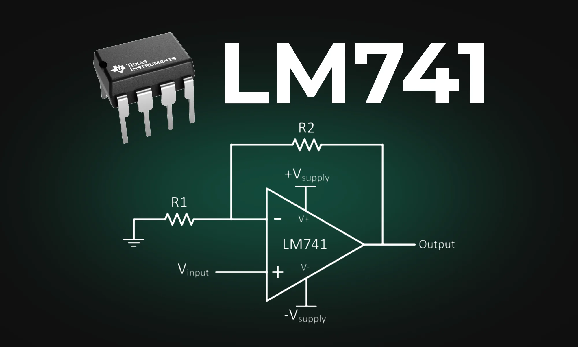
The blog post provides an in-depth look at the LM741 pinout diagram, explaining the functions of each pin, including inverting and non-inverting inputs, and comparing the LM741 to the LM324. It also covers various applications of the LM741 as an amplifier and a comparator.
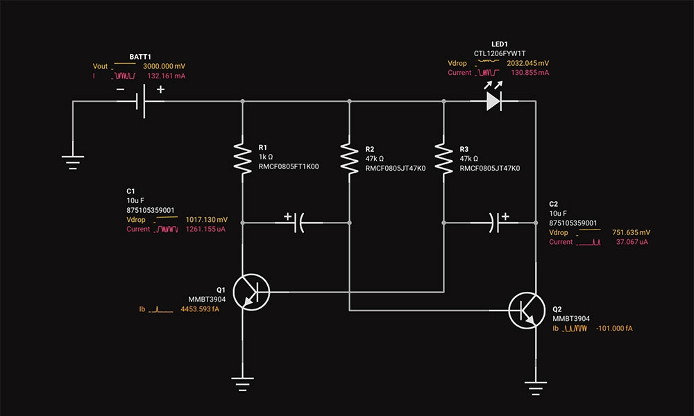
Circuit simulation is a crucial tool in electronic design. It uses software to predict how circuits will perform, saving time and money. Popular options like Flux, LTSpice, and CircuitMaker offer powerful features.

Electronics, whether in a phone or an industrial motor, face potential threats from unchecked electrical currents. Our guide introduces protection circuits, the essential safeguards that monitor and respond to such electrical anomalies.
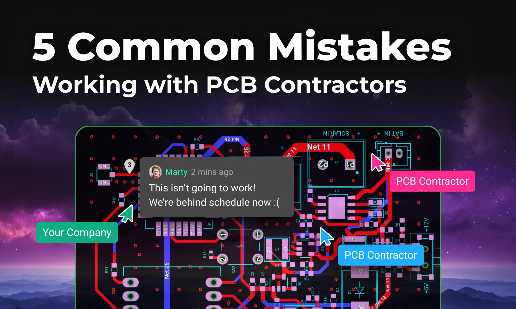
In this post, we’ll explore five common mistakes companies make when contracting PCB design and how you can avoid them by using tools like Flux to keep your project on track, from concept to completion.

Delve into the essentials of circuit diagrams, exploring the various electronics symbols and their roles in design, while also offering practical advice for effective use of diagramming tools like Flux.
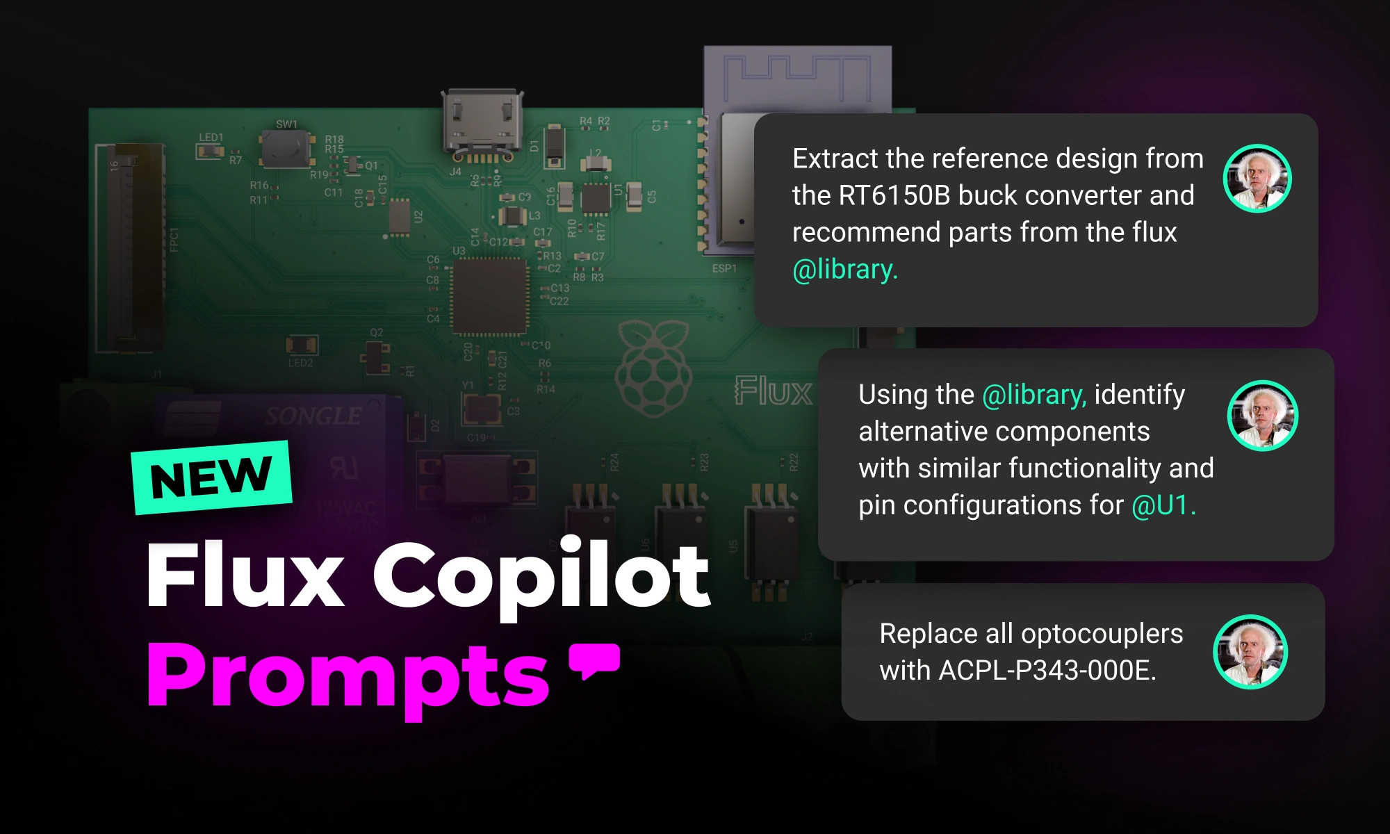
With the latest release of Copilot it isn’t just smarter—it’s hands-on, placing components and applying bulk changes to your project instantly. But to get the most out of it, knowing how to craft the right prompt is key.
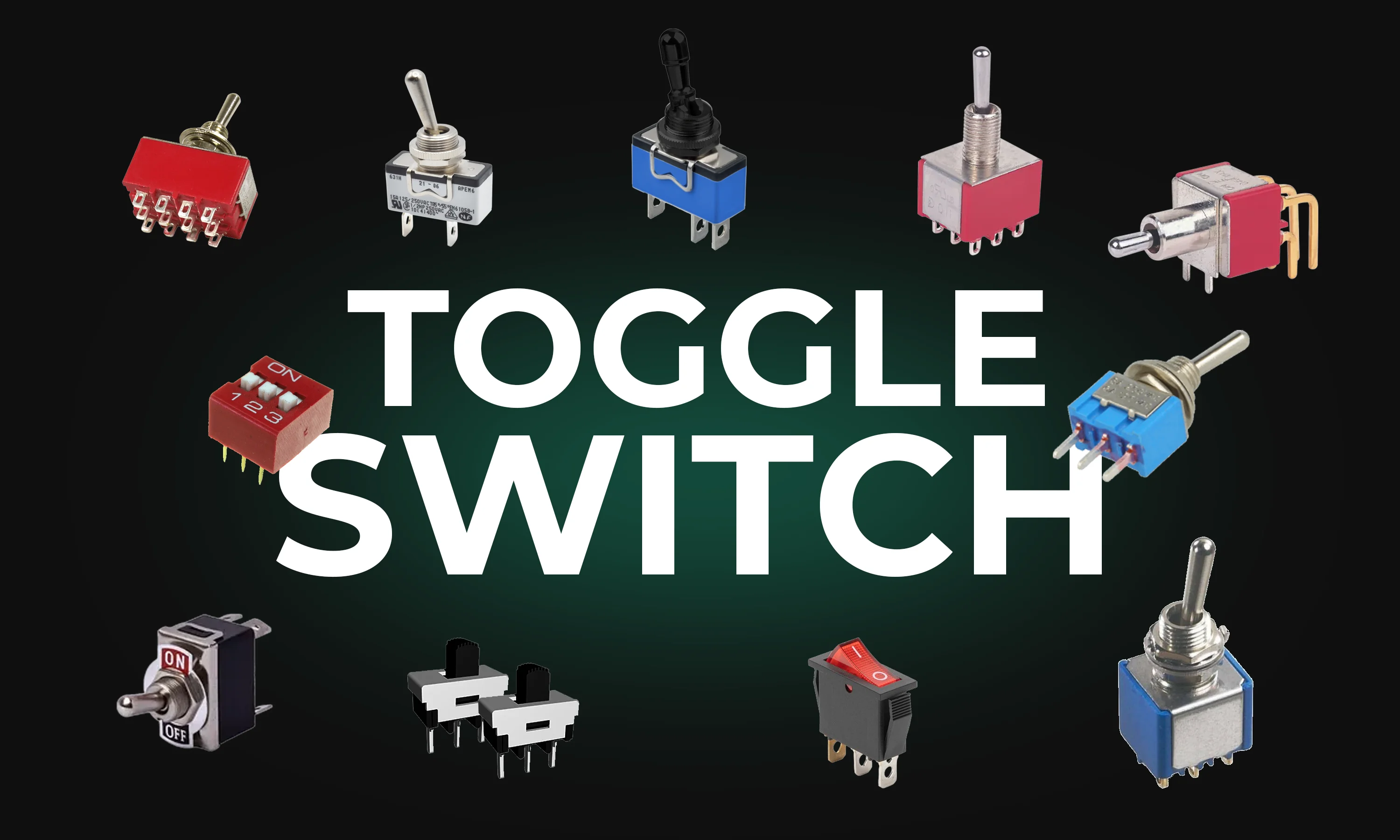
This guide explores toggle switches, their types, and applications in electronics. Learn how they work and find the right one for your project.